I. Equipment Definition
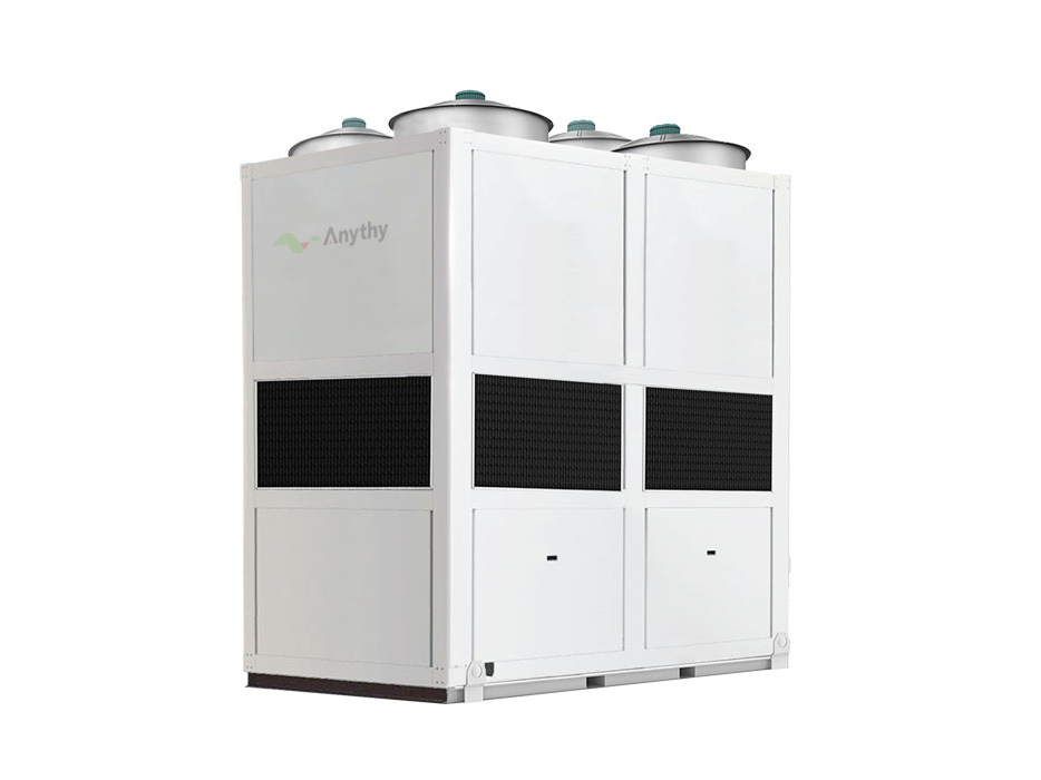
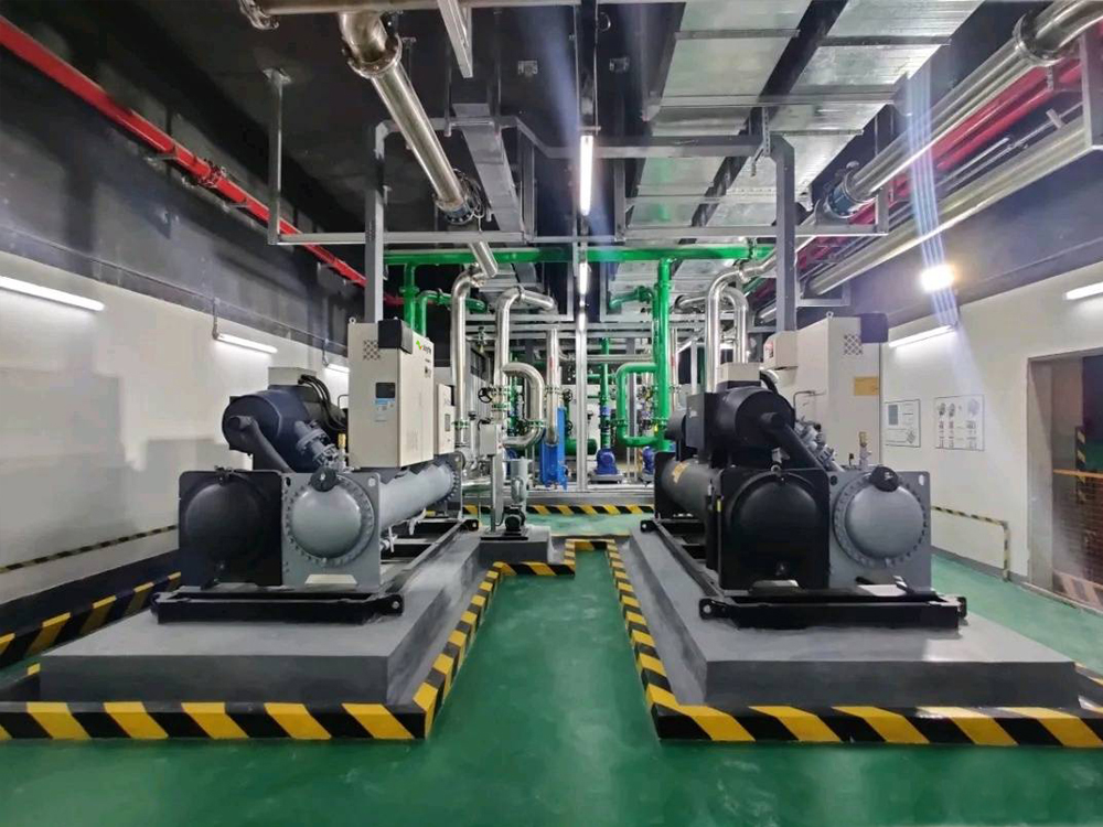
An air‑bearing evaporative‑cooled centrifugal chiller integrates air‑bearing oil‑free centrifugal compressor and all‑in‑one evaporative condenser. It is a large‑size integrated oil‑free chilled‑water main unit combining “centrifugal chiller main unit + cooling tower + spray cooling pump” within one single cabinet. No external separate cooling tower, cooling‑water pump or cooling‑water piping network is required.
Adopting air‑bearing bearing technology (static/dynamic air‑bearing), gas film formed by refrigerant vapor supports the rotor to realize oil‑free operation with zero mechanical friction. It belongs to oil‑free centrifugal chiller. R134a is the mainstream refrigerant; low‑GWP eco‑friendly refrigerants are optional. Single‑unit cooling capacity generally ranges from 250 kW to 2200 kW. Capacity expansion is realized by multi‑module parallel connection. It is widely applied in large‑scale commercial‑industrial and data‑center cooling projects.
Brief comparison among related models:
- Evaporative‑cooled scroll chiller: scroll compressor for small‑to‑medium capacity, oil‑lubricated.
- Air‑bearing evaporative‑cooled chiller: air‑bearing oil‑free centrifugal compressor for medium‑to‑large capacity, oil‑free system.
- Magnetic‑levitation evaporative‑cooled chiller: oil‑free centrifugal compressor with magnetic‑levitation bearing for rotor electromagnetic suspension.
II. Working Principle
1) Refrigerant Vapor‑Compression Cycle
- Air‑bearing variable‑speed centrifugal compressor: High‑speed impeller boosts pressure of low‑temperature low‑pressure refrigerant vapor. Air‑bearing creates micron‑scale gas film between rotor and bearing for levitation with oil‑free & friction‑free operation. Permanent‑magnet variable‑frequency motor realizes stepless load regulation.
- Integrated evaporative condenser (core heat‑rejection component): Built‑in spray pump sprays water from collecting tank onto outer coil surface to form uniform water film. Axial‑flow fans force air transversely across coils. Heat inside coils is removed by latent‑heat evaporation of water film, and high‑temperature gaseous refrigerant condenses into high‑pressure liquid.✅ Key advantage: Condensing temperature approaches outdoor wet‑bulb temperature, substantially lower than air‑cooled centrifugal chillers.
- Electronic expansion valve / economizer assembly: High‑pressure liquid refrigerant is throttled to low‑temperature low‑pressure gas‑liquid two‑phase state. Some models are equipped with economizer for sub‑cooling to improve cooling capacity and energy efficiency.
- Flooded / falling‑film evaporator: Refrigerant absorbs heat from chilled water and supplies 5‑12 ℃ chilled water to air‑conditioning terminals or process equipment. Heated refrigerant vaporizes and returns to compressor for continuous circulation.
Schematic logic:Chilled‑water circulation (external cooling supply) | Refrigerant circulation (internal oil‑free compression cycle) | Spray‑water circulation (unit self‑evaporative heat rejection)
III. Core Structural Composition
- Air‑bearing variable‑speed centrifugal compressorStatic/dynamic air‑bearing, high‑speed permanent‑magnet variable‑frequency motor. No lubrication oil system, no oil separator, no oil filter. Stepless variable‑frequency load adjustment for wide‑range working conditions. Faulty compressor can be isolated; multi‑compressor units allow partial‑load running upon single‑component failure.
- Evaporative condenser (coils + spray system + water eliminator + axial‑flow fan + bottom collecting tank)Corrosion‑resistant stainless‑steel / galvanized‑steel coils. Water baffles and eliminators reduce water drift. Built‑in interfaces for automatic water make‑up, overflow and blow‑down. Optional on‑line automatic coil‑cleaning device.
- Evaporator: High‑efficiency flooded / falling‑film heat exchanger producing 5‑12 ℃ chilled water.
- Throttling & sub‑cooling components: High‑precision electronic expansion valve. High‑grade units adopt economizer for secondary sub‑cooling for better heat‑exchange performance.
- Built‑in spray circulation pump: No external cooling pump required.
- Intelligent PLC control systemIndependent circuit protections including high/low‑pressure, anti‑freezing, water‑flow, overload, water‑shortage and bearing‑condition monitoring. Remote monitoring, multi‑unit module linkage and AI‑based load optimization are supported.
IV. Main Advantages
- Ultra‑high comprehensive energy efficiencyDual energy‑saving benefits: air‑bearing oil‑free centrifugal compressor delivers excellent IPLV; combined with evaporative‑condensing feature, condensing temperature is much lower than air‑cooled centrifugal chillers. It saves 20‑35 % power compared with air‑cooled air‑bearing chillers. Compared with conventional water‑cooled screw systems, extra energy consumption of cooling‑tower fans and cooling‑water pumps is eliminated, with overall IPLV reaching 9.0‑10.5.
- Oil‑free maintenance‑friendly & high reliabilityOil‑lubrication circuit is completely eliminated. No risk of heat‑exchanger oil fouling; no oil‑filter replacement. Bearings operate nearly wear‑free under normal conditions, extending service life and cutting annual O&M costs.
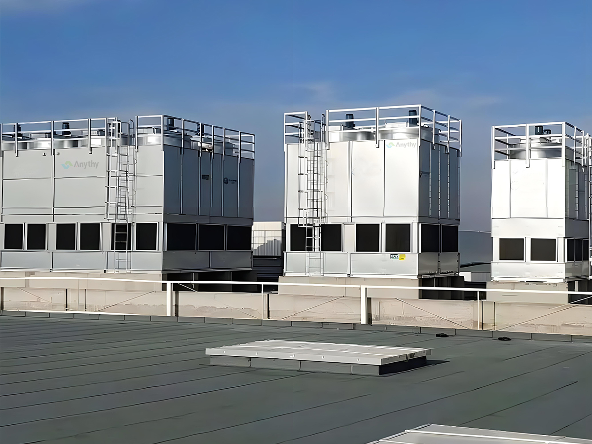
- Integrated design for simple installationFully pre‑fabricated in factory. Only chilled‑water piping and power supply connections are required on site. No equipment room or separate cooling tower needed. Suitable for open‑air installation on rooftops or open ground.
- Excellent water‑saving performanceWater consumption is only 1/4‑1/5 of conventional open‑tower water‑cooled systems, better than traditional water‑cooled solutions for water‑scarce large‑scale projects.
- Modular capacity expansion & fault‑tolerant operationMulti‑compressor / multi‑unit parallel connection. Single‑compressor failure will not shut down the whole system. Smaller footprint than combined “water‑cooled centrifugal main unit + cooling tower”.
- Lower noise than conventional screw chillersAir‑bearing compressor operates with zero mechanical friction and vibration; unit noise mainly comes from top‑mounted axial‑flow fans.
V. Disadvantages & Application Limitations
- Evaporative water consumption still exists: Not applicable for totally water‑free sites with zero water make‑up allowed. Evaporative heat‑exchange capacity drops slightly in high‑humidity coastal regions.
- Water‑treatment maintenance for spray‑water circuit: Circulating spray water tends to scale and breed algae. Regular blow‑down and water‑treatment chemical dosing are mandatory. Coil scaling will severely degrade unit efficiency.
- Strict winter anti‑freezing requirements: For outdoor installation, spray water tank and pipelines shall be drained or equipped with electric heat‑tracing during shutdown. Special evaluation is required for cold northern regions.
- High initial procurement cost: Air‑bearing centrifugal compressor costs higher than scroll and conventional screw compressors.
- Water‑drift risk: Water mist drift occurs when water eliminators age. Moisture‑sensitive electrical equipment shall not be arranged nearby.
- Brief mechanical contact during start‑stop: Rotor touches bearing for a short moment at start‑stop. Frequent‑start‑stop scenarios need proper application assessment.
VI. Typical Application Scenarios
✅ Recommended Applications‑ Central‑air‑conditioning cooling sources for large‑scale commercial complexes, airports, exhibition centers, hospitals, large‑scale hotels and office buildings‑ Medium‑&‑large‑size IDC & computing‑room cooling for low‑PUE pursuit‑ Large‑scale industrial process cooling: pharmaceutical, electronics, chemical constant‑temperature workshops‑ Large‑scale retrofit projects with site constraints, no space for equipment room or external cooling tower‑ Large‑scale projects with limited water supply but allowing minor water make‑up, pursuing high annual comprehensive efficiency
❌ Not‑Recommended Applications‑ Remote field sites in extreme drought with zero water‑make‑up possibility‑ Sites with long‑term severe winter frost without reliable anti‑freezing measures and proper O&M conditions‑ Environments with strong acid‑alkali corrosive gas without customized anti‑corrosion treatment‑ Small‑capacity projects (cooling capacity < 250 kW; evaporative‑cooled scroll chiller provides better cost‑effectiveness)
VII. Horizontal Comparison of Evaporative‑Cooled Chiller Series
表格
| Comparison Item | Evaporative‑Cooled Scroll Chiller | Air‑Bearing Evaporative‑Cooled Chiller | Magnetic‑Levitation Evaporative‑Cooled Chiller |
|---|
| Compressor Type | Scroll compressor (oil‑lubricated) | Air‑bearing oil‑free centrifugal | Magnetic‑levitation oil‑free centrifugal |
| Single‑unit Cooling Capacity | 80‑650 kW | 250‑2200 kW | 250‑2200 kW |
| Lubrication Mode | Oil‑lubricated | Gas‑film levitation, oil‑free | Electromagnetic levitation, oil‑free |
| Part‑load IPLV | Medium | Very high | Very high |
| Initial Investment | Low | High | Very high |
| Annual Maintenance | Routine maintenance including oil‑system work | Only spray‑water maintenance (oil‑free) | Only spray‑water maintenance (oil‑free) |
| Start‑Stop Feature | Frequent start‑stop allowed | Brief bearing contact on start‑stop | Zero contact; frequent start‑stop allowed |
| Application Scale | Small‑&‑medium commercial‑industrial | Large‑scale public buildings & data centers | Large‑scale public buildings & data centers |
VIII. Unit Selection & O&M Key Points
- Selection basis: Adopt local summer design wet‑bulb temperature as selection benchmark instead of dry‑bulb temperature only. Reserve 10‑15 % cooling‑capacity margin for high‑temperature & high‑humidity zones. Prefer evaporative‑cooled scroll chiller for cooling capacity below 250 kW.
- Water‑quality control: Softened water is recommended for spray water; perform regular blow‑down. Clean condenser coils at least once per year; on‑line automatic cleaning device is optional.
- Noise control: Noise‑reduction enclosure shall be applied for units near residential areas due to top‑mounted axial‑flow fans.
- Refrigerant: Low‑GWP eco‑friendly refrigerants are preferred for new projects.
- Control strategy: Intelligent load distribution among multiple compressors to balance component wear. Avoid excessive frequent start‑stop for air‑bearing units.
- Anti‑freezing: Reliable freeze‑protection measures for spray‑water tank and pipelines are mandatory for outdoor‑installed units.
Precautions for Unit Use
Installation precautions
1. When lifting, positioning, and installing the unit, safety must be taken into account to prevent collisions and ensure the integrity of the equipment.
2. If the unit is installed outdoors, efforts should be made to avoid exposure to wind and rain (except for rainproof types), direct sunlight, or other heat sources that directly radiate; The computer room environment must be kept dry, clean, and ensure good ventilation, leaving space for unit maintenance and upkeep.
3. For air-cooled units, please ensure that there are no obstructions around the unit and reserve 1 meter of space; There is no obstruction within 2 meters of the top of the unit to ensure good ventilation.
4. It is recommended to install the unit on a strong and level ground, and install shock-absorbing rubber pads under the unit chassis to correct the level of the unit. If there are anchor bolts, they must be installed and fixed.
5. The circulating water pump used in conjunction with the unit should be selected and installed according to the data requirements such as water flow rate and water resistance required by the unit.
6. The water pump must be installed in front of the inlet of the unit, and it is recommended to install a filter at the inlet of the water pump to prevent foreign objects from entering the heat exchanger of the unit; If the unit is installed in areas with poor water quality, water treatment must be carried out first to avoid damage to the heat exchanger.
7. It is recommended to install valves, water pressure gauges, thermometers, water flow switches, and other equipment for the water pipeline system connecting the unit, in order to facilitate the inspection and maintenance of the unit's daily operation.
8. To prevent air from being trapped in the water system, the air must be completely discharged before starting the compressor.
9. The chilled water pipeline must be insulated properly to avoid loss of cooling capacity, condensation, and freezing.
10. The weight of the system connection pipeline shall not be borne by the machine body. Rubber shock-absorbing flexible joints and gate valves shall be installed at the inlet and outlet of the unit to avoid vibration and facilitate maintenance.
11.When configuring wires for the unit, wires with slightly larger cross-sections (with margin) should be selected according to the power consumption, and reliable electronic control components and grounding power sources should be installed to prevent accidents such as overload and leakage.
12. As the unit is equipped with reverse phase and phase loss protection, attention must be paid to whether the line phase is correct during wiring installation. The unit cannot operate normally when the phase is misconnected or missing.
13. The operator of the unit must observe the operation status of the unit at all times. Once any abnormal situation is found, please promptly troubleshoot. Forced operation will inevitably cause damage to the unit.
Precautions for operation:
1. Before starting up, check whether all water outlets and pipelines of the unit have been correctly installed and connected.
2. Before starting up, check if the power supply of the unit is connected and if the phase sequence is correct.
3. Before starting up, ensure the safety of the power and water sources. Please carefully refer to the equipment operation manual and strictly follow the instructions for use and operation.
Maintenance precautions:
1. Regularly replace the water in the water tank (it is recommended to replace it every 2 months).
2. Regularly clean the radiator of the unit. For air-cooled units, it is recommended to clean the radiator every 3 months; It is recommended to clean the shell and tube condenser and cooling tower of water-cooled units every 6 months (if the usage environment or water quality is poor, it is recommended to shorten the cleaning cycle).
3. If the unit is not used for a long time, please turn off the main power supply; When the ambient temperature is below 0 ℃ and the unit is shut down for more than 6 hours, the unit and pipelines may freeze, and the damage caused by this is not covered by the warranty. The best way to avoid pipeline freezing is to completely drain all the water in the unit system!
4. Regularly check the water quality on site to ensure that the water source is qualified (pH ≈ 7). If it contains corrosive substances and causes damage to the unit, it is not covered by the warranty.
5. When the unit encounters unavoidable faults during use, please inform our company of the unit model, component name, and other information so that we can provide you with services more quickly.
6. During the warranty period, our company promises to provide free maintenance services for the unit (excluding human damage, improper use, natural disasters, and uncontrollable factors).
Warning: This unit is a high-voltage, highly specialized mechanical equipment, and should be operated correctly by professional technicians strictly in accordance with the "User and Installation Manual".





 +86 18503011521